The idea: a force on a current turns a coil
A wire carrying a current in a magnetic field is pushed sideways. Bend the wire into a loop, put it between the poles of a magnet, and the two long sides of the loop are pushed opposite ways: one up, one down. Two opposite forces on either side of an axle make a torque, and the loop turns. That is an electric motor. Turn the same loop by hand instead and the field pushes charge round it: a generator.
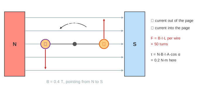
The canvas looks along the axle. The two circles are the coil's long sides, a (orange) and b (purple); ⊙ means current coming out of the page, ⊗ going in. Below the coil is the ring that connects it to the battery, drawn on its own so you can see it. The graphs plot the current in the coil and the torque against the coil's angle α.
The force on a wire: F = B·I·L
A straight wire of length L carrying current I across a field B feels a force
F = B · I · L (direction: I × B)at right angles to both the wire and the field. It is the same Lorentz force that bends a moving charge, added up over all the charges moving in the wire. On the canvas B = 0.4 T, I = 2 A, L = 0.10 m and the coil has N = 50 turns, so each side feels 50 × 0.4 × 2 × 0.10 = 4 N. The field is horizontal and the wires run along the axle, so the force is always straight up or straight down, whatever the coil's angle.
Torque and the lever arm
The force does not change as the coil turns, but its lever arm does: the sideways distance from the axle to the line of the force, r·|cos α|, drawn in grey on the canvas. With two sides and the area A = L·2r = 0.005 m²:
τ = 2 · F · r · cos α = N · B · I · A · cos α| Coil angle α | Lever arm | Torque τ (2 A) |
|---|---|---|
| 0°, plane along B | 25 mm, the full radius | 0.200 N·m, the most |
| 45° | 17.7 mm | 0.141 N·m |
| 90°, plane across B | 0 | 0, the dead spot |
At 90° the forces pull straight outwards along the coil, as if trying to stretch it. They no longer turn it at all.
The dead spot and the commutator
Push the coil past 90° and side a is now on the left of the axle, but its current, and so its force, has not changed: it is still pushed up, which now turns the coil back. With plain slip rings, one ring per end of the coil, a DC motor swings past 90°, gets pulled back and stops there (Demo: no commutator, stuck at 90°).
The fix is a split-ring commutator: one ring cut into two halves, each joined to one end of the coil, turning with it. Two fixed brushes press on it. The gaps pass the brushes exactly at the dead spot, so every half turn the brushes swap halves and the current in the coil reverses. Whichever side is on the right always carries ⊙ and is always pushed up, and the torque never changes sign (Demo: one full turn with the commutator).
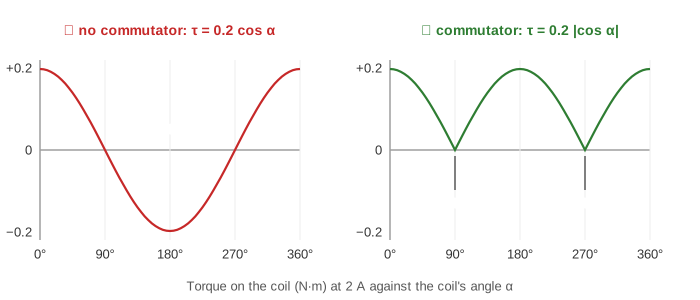
The torque still drops to 0 twice a turn, so a one-coil motor runs bumpily and can stall on the dead spot. Real motors have many coils, each at a different angle, and a commutator with many segments, so some coil is always near its best angle.
More current, more torque
Every term in τ = N·B·I·A·cos α is a dial. Doubling the current to 4 A doubles each force to 8 N and the peak torque to 0.4 N·m (Demo: double the current, double the torque). More turns, a stronger magnet or a bigger coil do the same. Over one full turn with the commutator the average torque is 2/π of the peak, 0.127 N·m at 2 A, and the work done is the area under the torque curve, 4 × N·B·I·A = 0.8 J per turn.
The same machine as a generator
Take the battery away, put a meter in its place and turn the coil by hand. Now the sides move through the field, and by Faraday's law an EMF appears in the coil: ε = N·B·A·ω·cos α. At 50 Hz (ω = 314 rad/s) its peak is 50 × 0.4 × 0.005 × 314 = 31.4 V, at α = 0° where the sides cut straight across the field lines. At 90° they slide along the lines and ε = 0.
- With slip rings the meter sees the coil's own EMF: positive for half a turn, negative for the other half. That is AC, and it is how power-station alternators work (Demo: generator with slip rings, AC).
- With the commutator the ends are swapped just as the EMF changes sign, so the meter only sees positive humps: pulsing DC, the old car dynamo (Demo: generator with commutator, pulsing DC).
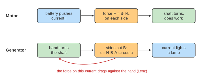
Look at side a at α = 0° in both modes, turning the same way. The motor's current there is ⊙; the generator's is ⊗, the other way. The force on the generator's current therefore points against the turning (Lenz's law): you have to work to keep it going, and that work becomes the electrical energy. The other way round, a running motor is a generator too: its spinning coil makes a back EMF that opposes the battery. The faster it spins, the bigger the back EMF and the smaller the current, which is why a motor draws its largest current when it starts or stalls.
Kinds of motor
| Motor | How the current in the coils is switched | Where |
|---|---|---|
| Brushed DC | Split-ring commutator and carbon brushes, as on the canvas | Toys, car wipers and starter motors, cheap fans |
| Brushless DC | Magnets on the rotor, coils fixed; electronics switch the coils using a position sensor | Drones, computer fans, hard drives |
| AC induction | AC in fixed coils makes a rotating field; it induces currents in the rotor | Pumps, washing machines, many electric cars |
What the page leaves out
The coil turns in fixed 15° steps; the page does not compute its speed from its inertia, the load and the back EMF, and the motor's current stays at 2 A or 4 A. The field is uniform and the coil has one winding position; real motors use curved poles, an iron core and many coils. Brush sparking, friction and the resistance of the coil are left out, and the generator's meter draws no current, so its drag is drawn only as a direction.