The idea: a one-way valve for current
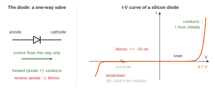
The socket gives alternating current: the voltage swings positive and negative 50 times a second. Chips, LEDs and batteries need direct current: one polarity, steady. The part that does the conversion is the diode, a one-way valve. Current flows from its anode to its cathode (the bar in the symbol) once the forward voltage passes about 0.7 V, and is blocked the other way.
The canvas uses a 12 V transformer secondary (peak 16.97 V), a 100 Ω load and up to four diodes, and shows the circuit, one diode's I-V curve, a scope with vin and vout, and the numbers measured over the last cycle. Green diodes and wires are carrying current right now.
The diode's I-V curve
A silicon diode is a p-n junction. Its current follows the Shockley equation I = IS (eV / nVT − 1), with a tiny saturation current IS (10 nA here), an ideality factor n between 1 and 2, and the thermal voltage VT ≈ 25.85 mV at room temperature. Because of the exponential, the current is negligible up to about 0.5 V and then shoots up: every extra 0.05 V roughly triples it (Demo: diode I-V, forward 0.7 V, reverse blocks).
| V across the diode | Current (IS = 10 nA, n = 1.8) | What it means |
|---|---|---|
| −1 V or −2 V | ≈ −10 nA | reverse bias: blocks |
| 0.5 V | ≈ 0.5 mA | barely on |
| 0.6 V | ≈ 4 mA | the knee |
| 0.7 V | ≈ 34 mA | conducting |
| 0.75 V | ≈ 100 mA | three times more for 0.05 V |
So for circuit work a conducting silicon diode is treated as a fixed 0.7 V drop (0.3 V for a Schottky diode, about 2 V for a red LED), and a reverse-biased one as an open switch. That is the model the circuit on the canvas uses. Reverse bias holds until the breakdown voltage: 50 V to 1000 V for a 1N400x rectifier diode, a few volts for a Zener diode, which is built to break down on purpose and is used as a voltage reference.
Half-wave rectifier
Put one diode in series with the load. When the top of the transformer is positive, D1 is forward biased and the load gets vin − 0.7 V, up to 16.27 V. When it is negative, D1 is reverse biased, the load gets 0 V and the whole negative voltage sits across D1 (Demo: half-wave, only the top half passes). The output is DC in the sense that it never goes negative, but it is zero half the time: its average is only about (Vpeak − 0.7) / π, 5.0 V here.
Full-wave bridge rectifier
A bridge rectifier uses four diodes so that both halves of the wave push current the same way through the load. When the left side of the source is +, D1 and D4 conduct; when the right side is +, D2 and D3 do. The other pair is reverse biased each time. The current through R always flows from the + rail down to the − rail (Demo: bridge, both halves flipped up).
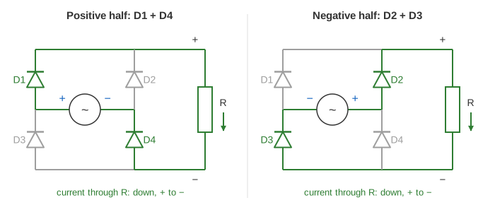
The price is two diode drops instead of one: the peak is 16.97 − 1.4 = 15.57 V. In return the output has two humps per cycle instead of one, so its average almost doubles (9.3 V) and its ripple frequency is 100 Hz instead of 50 Hz, which makes it much easier to smooth. A centre-tapped transformer with two diodes is the other full-wave design; it saves two diodes but needs twice the winding.
Smoothing capacitor and ripple
A capacitor across the load charges up to the peak and then feeds the load while the rectified input is lower. During that time every diode is off: the input is below the capacitor's voltage. The capacitor discharges through R with time constant RC and sags until the next peak catches up with it. The sag is the ripple. The diodes now conduct only in short bursts just before each peak, which is why a rectifier's input current comes in pulses.
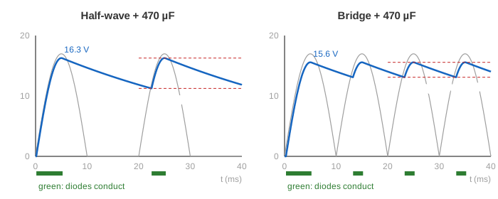
For a ripple that is small next to the output, the capacitor loses a charge I × (1/f) between peaks, so ΔV ≈ I / (f · C) = V / (f · R · C), with f = 50 Hz for half-wave and 100 Hz for a bridge. The rule of thumb is a little pessimistic because the capacitor is topped up before the next peak.
| Circuit | C | Peak out | Lowest | Ripple ΔV | Average | Demo |
|---|---|---|---|---|---|---|
| half-wave | none | 16.27 V | 0 V | 16.27 V | 5.00 V | half-wave, only the top half passes |
| bridge | none | 15.57 V | 0 V | 15.57 V | 9.32 V | bridge, both halves flipped up |
| half-wave | 470 µF | 16.27 V | 11.30 V | 4.97 V | 13.71 V | half-wave + 470 µF, big ripple |
| bridge | 470 µF | 15.57 V | 13.09 V | 2.48 V | 14.38 V | bridge + 470 µF, half the ripple |
| bridge | 2200 µF | 15.57 V | 14.95 V | 0.62 V | 15.26 V | bridge + 2200 µF, nearly flat DC |
Choosing the parts
- Capacitor: pick C from the ripple you can accept, C ≈ I / (f · ΔV). For 0.16 A, 100 Hz and 1 V of ripple that is 1600 µF; the next standard value is 2200 µF.
- Peak inverse voltage (PIV): the reverse voltage a diode must survive. In a bridge it is about Vpeak; in a half-wave rectifier with a capacitor it is about 2 × Vpeak, because the charged capacitor holds the cathode up while the anode swings to −Vpeak.
- Surge current: an empty capacitor looks like a short circuit at switch-on, so the first peaks drive a large current through the diodes. Real supplies limit it with a resistor or an NTC thermistor.
- Regulation: the ripple and the load still move the output. A linear regulator (like a 7812) or a switching converter after the capacitor gives a steady voltage.
See also AC vs DC for where the AC comes from and why the grid uses it, and RLC Circuits for how a capacitor charges and discharges with time constant RC.
What the page leaves out
The circuit uses the fixed 0.7 V diode model rather than the full exponential curve, so the drop does not grow with current, and the charging current is not limited by any resistance (a real transformer's winding resistance rounds the peaks and stretches the conduction bursts). Also left out: the diode's reverse-recovery time, the transformer itself, surge current at switch-on, three-phase rectifiers, controlled rectifiers (thyristors), voltage regulators and the switching converters in modern chargers.