The idea: charges that slosh send out waves
A charge sitting still has an electric field around it, and a charge moving steadily carries its field along. A charge that accelerates does something more: it shakes its field, and the shake travels outward at the speed of light as an electromagnetic wave (see Electromagnetic Waves).
An antenna makes charges accelerate on purpose. A dipole is two metal rods end to end, fed in the middle with an alternating current. Each half period the electrons rush from one rod to the other: one tip turns positive, the other negative, then the other way round. Every period the antenna sends out one crest and one trough, so the rings on the canvas are one wavelength λ = c/f apart and move out at c (Demo 1).
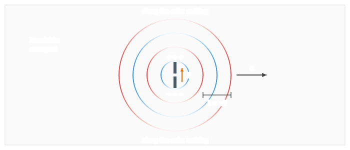
The half-wave dipole
The rods work best when the whole antenna is half a wavelength long: then the current that runs up and back fits the antenna exactly once per half period, like a string on its fundamental (see Standing Waves). That is why antenna sizes follow the frequency:
| Signal | f | λ = c/f | half-wave dipole |
|---|---|---|---|
| FM radio | 100 MHz | 3.00 m | 1.50 m |
| TV | 600 MHz | 50 cm | 25 cm |
| Wi-Fi | 2.4 GHz | 12.5 cm | 6.25 cm |
No radiation along the axis: the sin²θ pattern
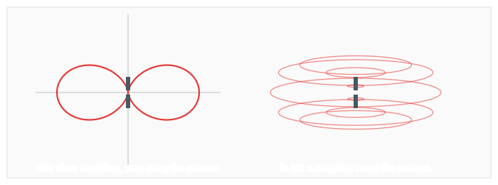
Seen from a direction at angle θ to the antenna, only the part of the charges' motion across the line of sight shakes the field sideways, and that part is proportional to sin θ. Far away the field is
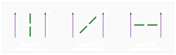
E ∝ sin θ · cos(kr − ωt) / r intensity ∝ sin²θ / r²Broadside (θ = 90°) the antenna sends its strongest wave; along its own axis (θ = 0°) it sends nothing at all (Demo 2); at 45° the field is sin 45° = 0.71 of the best and the power half (Demo 3). In 3D the pattern is a doughnut around the antenna. That is why broadcast antennas stand vertical: they send to the horizon, not to the sky.
Polarization and the receiving antenna
Far from the antenna E lies in the plane of the antenna and at right angles to the direction of travel: the wave is linearly polarized along the antenna. A receiving antenna works the same way backwards: the field pushes the electrons along its rods and drives a current. Only the part of E along the rods counts, so the signal goes as cos φ, φ being the angle between the rod and E. Turned at right angles it receives nothing (Demo 4), just like a polarizer turned across the light (see Polarizers). The field also falls off as 1/r: half as far away, the signal is twice as strong and the power four times (Demo 5).
Where you meet it
| Where | What the antenna does |
|---|---|
| FM and TV aerials | Dipoles about λ/2 long, often with extra rods (Yagi) to aim the pattern |
| Wi-Fi routers and phones | Short antennas a few centimetres long; turning a router's antennas changes coverage |
| Car and radio whips | A quarter-wave rod over the metal body, which acts as the other half |
| Radio telescopes | Receiving antennas; their dishes collect the weak waves onto a small dipole or horn |
What the page leaves out
The page draws the far field of a short dipole, sin θ·cos(kr − ωt)/r, and leaves out the near field close to the antenna (r below about λ/2), where the field also stores energy that comes back every cycle. A real half-wave dipole has a slightly narrower pattern than sin²θ, a feed resistance of about 73 Ω, and loses some power as heat. The magnetic field (at right angles to E, around the antenna), ground reflections and arrays of antennas are not shown.