The idea: one draw call, eight stages
A program asks the GPU to draw a triangle with one call, for example
glDrawArrays(GL_TRIANGLES, 0, 3). The GPU then runs the three vertices through a fixed chain
of stages called the graphics pipeline. Two stages run code you write: the
vertex shader and the fragment shader. The others are built into the
hardware and you only switch them on, off or set a mode.
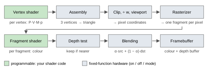
Each stage has its own page on this site: the transforms on Perspective Projection, the pixel test on Rasterization, the lighting a fragment shader computes on Phong Shading. This page shows how they fit together. The screen is a tiny 16 × 12 framebuffer, so every fragment and every depth value is on the canvas.
| stage | runs | input → output |
|---|---|---|
| vertex shader | your code, once per vertex | vertex → clip-space position |
| primitive assembly | fixed | 3 vertices → 1 triangle |
| clipping, ÷ w, viewport | fixed | triangle → 0, 1 or more triangles in pixels |
| rasterization | fixed | triangle → fragments (one per covered pixel) |
| fragment shader | your code, once per fragment | fragment → colour |
| depth test | fixed, on or off | keep or drop the fragment |
| blending | fixed, on or off | mix with the colour already there |
| framebuffer | memory | colour buffer + depth buffer |
The vertex shader: model, view, projection
A vertex starts in object space, the coordinates the modeller used. The vertex shader multiplies it by three matrices: M (model) places the object in the world, V (view) moves the world so the camera sits at the origin looking down −z, and P (projection) turns the view volume into clip space. In GLSL it is one line:
gl_Position = P * V * M * vec4(position, 1.0);
On the page M is a translation, the camera is at (0, 0, 2), and P is a perspective matrix with a 90° field of view, aspect 16 / 12, near plane 1 and far plane 3. Written out it gives xc = 0.75·x, yc = y, zc = −2·z − 3 and wc = −z. For vertex v0 of triangle A: object (−3, 1.4, 0) → world (−2, 1.4, 0) → eye (−2, 1.4, −2) → clip (−1.5, 1.4, 1, 2). (Demo 1: one triangle through every stage)
The shader runs once per vertex and every run is independent, so a GPU runs thousands of them at once (see GPU SIMT and warps). It can also pass extra values, called varyings (colour, normal, texture coordinates), on to the fragment shader.
Clipping before the divide
In clip space a point is inside the view volume when −w ≤ x ≤ w, −w ≤ y ≤ w and −w ≤ z ≤ w. The clipper checks this before dividing by w, and for a good reason: a point level with the camera has w = 0, and a point behind it has w < 0. Dividing would blow up or flip it to the wrong side of the screen.
Triangle C has c2 at eye z = 0, so its clip position is (0.3, 2.4, −3, 0). It fails the near plane (z < −w). The clipper cuts both edges that leave the volume. For edge c0–c2 the distance to the near plane, z + w, is 3 at c0 and −3 at c2, so the cut is at t = 3 / (3 − (−3)) = 0.5: a new vertex at clip (0.75, 0.4, −1, 1). The kept part has four corners, c0, c1, p4, p3, and is drawn as a fan of two triangles. (Demo 8: clipping at the near plane)
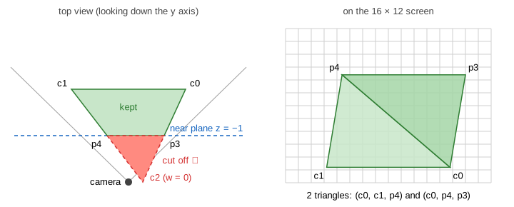
After clipping, every vertex has w > 0. The perspective divide gives normalized device coordinates (NDC) in −1…1, and the viewport transform maps them to pixels: xwin = (x + 1)·8, ywin = (1 − y)·6 and depth = (z + 1) / 2, a number from 0 (near plane) to 1 (far plane).
Rasterize, then shade each fragment
The rasterizer finds the pixel centres inside the triangle and makes one fragment for each, with a depth mixed from the three vertex depths (how: Rasterization). Triangle A gives 48 fragments with depths from 0.51 to 0.84; the canvas prints each one in its pixel. Then the fragment shader runs once per fragment and returns a colour. On the page it returns the triangle's colour; a real one would compute lighting or read a texture here.
Fragments are not pixels yet. A fragment is a candidate: the next two stages decide whether it reaches the framebuffer and how.
A second triangle: the depth test
The depth buffer keeps one depth per pixel, cleared to 1. With GL_DEPTH_TEST on and the default
GL_LESS, a fragment survives only if its depth is less than the stored one, and then its depth is
stored. Triangle B sits at depth 0.25, in front of A. It has 31 fragments and overlaps A in 15 pixels.
| draw order | depth test | second draw: pass / fail | overlap shows |
|---|---|---|---|
| A, then B | on | B: 31 / 0 | B ✓ |
| B, then A | on | A: 33 / 15 | B ✓ (same picture) |
| B, then A | off | A: 48 / 0 | A ✗ (the farther one) |
(Demo 2, Demo 3 and Demo 4.) In Demo 3 the 15 hidden fragments of A were still run through the fragment shader and then thrown away. GPUs avoid that waste with early-z: when the shader does not change the depth, the test runs before the shader. Drawing opaque objects roughly front to back makes it pay off.
Glass: blending and why order matters again
With blending on (glBlendFunc(GL_SRC_ALPHA, GL_ONE_MINUS_SRC_ALPHA)) the new colour is mixed
with the colour already in the pixel:
new = α·src + (1 − α)·dst
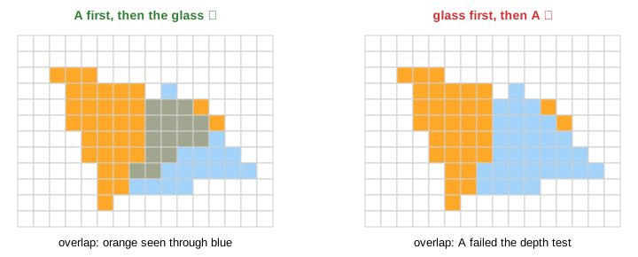
The glass version of B is blue (66, 165, 245) with α = 0.5. Over the orange of A (255, 167, 38) it gives (161, 166, 142); over the white background it gives (161, 210, 250). (Demo 7: one fragment of the glass, blended)
Now the order matters even with the depth test on. Draw A first and the glass second, and the overlap shows A through the glass. Draw the glass first, and it writes depth 0.25 into the overlap; A's 15 fragments there then fail the depth test, so A vanishes behind a pane that should be see-through. (Demo 5 and Demo 6.)
The usual recipe: draw all opaque objects first with depth writes on, then draw the transparent ones
sorted far to near, with the depth test on but depth writes off (glDepthMask(GL_FALSE)).
See also Rasterization: Edge Functions and the Z-Buffer for the pixel test, Perspective Projection for the divide by depth, Phong Shading for what a fragment shader computes, and Ray Tracing vs Rasterization for the other way to make an image.
See also Texture Mapping: UV, Bilinear, Mipmaps and Wrap for what a texture read in the fragment shader does: nearest or bilinear lookups, mipmap levels and wrap modes.
See also Shadow Mapping, which runs the pipeline twice: once from the light to store depths, then from the camera to test each point against them.
See also Polygon Clipping: Outcodes, Sutherland–Hodgman and Back Faces, which clips a polygon against one window edge at a time with the same four inside/outside cases and shows back-face culling by winding order.
What the page leaves out
Index buffers and vertex caches, back-face culling (off by default in OpenGL; all triangles here face the camera), tessellation and geometry shaders, perspective-correct interpolation of varyings, textures and mipmaps, the stencil test and scissor test, anti-aliasing with several samples per pixel, guard-band clipping (GPUs only really clip at the near and far planes), tile-based GPUs on phones, and double buffering of the framebuffer.