The idea: divide by the depth
A pinhole camera is a dark box with a tiny hole O. Light from a point P of the scene goes in a straight line through the hole and lands on the back wall. Put the camera at the origin, looking along the z-axis, so z is the depth of a point. The page draws the picture on the plane z = f in front of the hole instead of behind it: same picture, but upright. The number f is the focal length.
The ray from P = (x, y, z) to O crosses the plane z = f at the point P'. The two triangles in the figure are similar, so y'/f = y/z, and the same for x:
x' = f·x / z, y' = f·y / z.
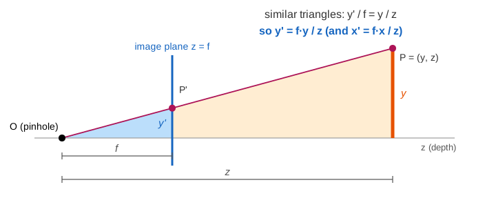
On the canvas, Trace Rays builds the picture this way: each corner of the scene sends a ray to O, the ray meets the image plane, and the image points are joined up. (Demo 1: rays through the pinhole)
Far is small: size ∝ 1/z
An object of size s at depth z comes out f·s/z in the picture. Twice as far, half as big. The four posts are all 2 tall, at depths 3, 6, 9 and 12. With f = 1.5:
| post | depth z | height in the picture 1.5·2/z | compared with post 1 |
|---|---|---|---|
| 1 | 3 | 1 | 1 |
| 2 | 6 | 1/2 | 1/2 |
| 3 | 9 | 1/3 | 1/3 |
| 4 | 12 | 1/4 | 1/4 |
That is why a row of equal posts, trees or lamp-posts seems to shrink toward a point. (Demo 2: far is small, posts shrink as 1/z)
Parallel lines meet at a vanishing point
Take a line through A with direction d = (dx, dy, dz), dz > 0. Its points are A + t·d. Their pictures are
f·(Ax + t·dx) / (Az + t·dz) → f·dx/dz as t → ∞,
and the same for y. The start A drops out: every line with direction d heads for the same point f·(dx/dz, dy/dz), the vanishing point of d. It is where the ray through O parallel to the lines hits the image plane. The rails and road edges all have d = (0, 0, 1), so they meet at (0, 0), the centre of the picture. (Demo 3: rails meet at the vanishing point)
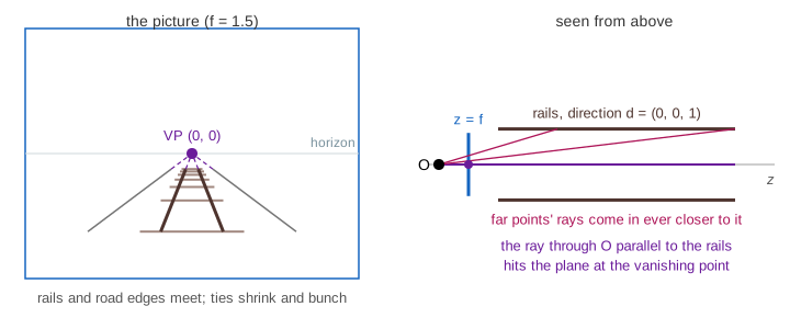
- Lines with dz = 0 (parallel to the image plane, like the ties and the posts) have no vanishing point: they stay parallel in the picture.
- Box C is turned 45°. Its sides have directions (1, 0, 1) and (−1, 0, 1), with vanishing points (f, 0) and (−f, 0) on the horizon y' = 0: two-point perspective. Run Trace Rays on the boxes, then look at the facts panel.
- Lines on flat ground (the rails, the road edges, the bottoms of the boxes) all have dy = 0, so their vanishing points lie on the line y' = 0: the horizon, at the height of the camera.
Straight stays straight, but nothing else is kept
A straight line in the scene comes out straight in the picture (the rays through it all lie in one plane through O, and that plane meets the image plane in a line). But the map is not linear: parallel lines meet, equal lengths come out different, and the midpoint of a segment does not go to the midpoint of its picture. The ties are evenly spaced on the ground and bunch up in the picture.
The matrix and the divide by w
Write P with a 4th coordinate 1 (homogeneous coordinates) and multiply by a 3 × 4 matrix:
[f 0 0 0]   [x]   [f·x]
[0 f 0 0] · [y] = [f·y]
[0 0 1 0]   [z]   [ z ]  = w
            [1]
This part is linear. The last step, divide by w, gives (f·x/z, f·y/z): all of the non-linear behaviour sits in that one division. For P = (−1.5, 1, 3) and f = 1.5 the product is (−2.25, 1.5, 3) and the divide gives (−3/4, 1/2). For P = (−0.5, 1, 6) the product is (−0.75, 1.5, 6): w is twice as big, so the point lands nearer the centre, at (−1/8, 1/4). (Demo 6: the matrix and the divide by z)
Graphics pipelines use the same trick with a 4 × 4 matrix that also keeps a depth value for the z-buffer, and the affine transforms (rotate, move) that place the camera are 4 × 4 matrices of the same kind, so the whole chain is one matrix product followed by one divide.
Perspective vs orthographic
Orthographic projection drops z instead of dividing by it: x' = x, y' = y, the matrix [1 0 0 0; 0 1 0 0; 0 0 0 1] and w = 1. Every ray is parallel to the z-axis. It is a linear map (a projection matrix), so it keeps parallel lines and ratios, but the picture no longer shows which things are far. (Demo 5: perspective vs orthographic)
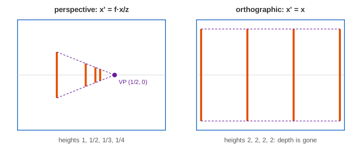
| perspective | orthographic | |
|---|---|---|
| rule | x' = f·x/z, y' = f·y/z | x' = x, y' = y |
| rays | all through the pinhole O | all parallel to z |
| far objects | smaller (1/z) | same size |
| parallel lines | meet at a vanishing point (if dz ≠ 0) | stay parallel |
| linear? | no: linear in homogeneous coordinates, then ÷ w | yes |
| used for | cameras, eyes, 3D games | engineering drawings, maps, CAD views |
Focal length: zoom and field of view
Every picture coordinate is f times something, so doubling f doubles the picture: a zoom. The picture window stays the same size (here 3.2 × 2.4), so less of the scene fits: the horizontal field of view is 2·atan(1.6/f).
| f | 0.5 | 1 | 1.5 | 2 |
|---|---|---|---|---|
| field of view | 145.3° | 116.0° | 93.7° | 77.3° |
Short f is a wide-angle lens, long f a telephoto lens. (Demo 4: zoom, f doubles)
See also Linear Transformations, Affine Transforms (homogeneous coordinates in 2D), Projection Matrix in 3D (the orthographic case), Projection Matrix, Changing Coordinates in 3D (moving the world into the camera's frame), Rotation Matrix in 3D and Composing Transforms.
What happens next, turning the projected triangles into pixels and keeping the nearest one, is shown in Rasterization: Edge Functions and the Z-Buffer.
See also Ray Tracing, which makes the image the other way round: one ray from the eye through each pixel instead of projecting each object.
What the page leaves out
The real picture behind the pinhole (upside down, at z = −f), lenses, focus and blur. Pixel coordinates: real cameras scale by the pixel size, move the origin to a corner and often flip y (the intrinsic matrix K), and OpenGL looks down −z instead of +z, which changes signs but not the idea. Placing the camera in the world (rotation and translation, the extrinsic matrix [R | t]), the 4 × 4 projection matrix with near and far planes and the z-buffer, clipping points behind the camera, lens distortion, and recovering 3D from two pictures (stereo, epipolar geometry).