The idea: look from the light first
A point is in shadow when something sits between it and the light. A rasterizer can't ask that question for one point at a time. Shadow mapping answers it with two passes. Pass 1 draws the scene from the light and keeps only depth: the shadow map. Pass 2 draws the scene from the camera; for each point it asks the map "did the light see something nearer than me?"
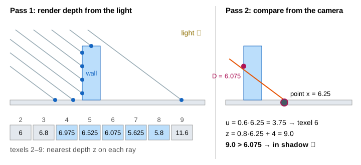
The page uses a 2D side view so every number fits: a floor from x = 0 to 15, a wall from x = 4 to 5 that is 3 high, and a directional light (the sun) travelling along d = (0.8, −0.6). The shadow map has 15 texels. The camera sees 28 points on the floor. Where the map sits among the GPU stages is on The Graphics Pipeline.
Pass 1: depth from the light
The light is a camera too. For a directional light it uses an orthographic projection: a rotation into the light's frame, then a scale. On the page that gives two light-space coordinates:
u = 0.6x + 0.8y (across the light) and z = 0.8x − 0.6y + 4 (depth along the light)
Texel i covers u from 0.6i to 0.6i + 0.6, and its ray runs through the centre u = 0.6i + 0.3. It keeps the z of the first surface on that ray, the same rule as the z-buffer. Texel 2 meets the floor at (2.5, 0): z = 6.0. Texel 4 meets the wall's face at (4, 0.375): z = 6.975, and the floor behind it is never stored. Texels 4–7 see the wall's face, texel 8 its top (5.8), all others the floor. (Demo 1: pass 1, render the shadow map)
| texel | 0 | 1 | 2 | 3 | 4 | 5 | 6 | 7 | 8 | 9 | … | 14 |
|---|---|---|---|---|---|---|---|---|---|---|---|---|
| stored z | 4.4 | 5.2 | 6.0 | 6.8 | 6.975 | 6.525 | 6.075 | 5.625 | 5.8 | 11.6 | … | 15.6 |
Pass 2: to light space and compare
Now the camera draws the scene. Each visible point is multiplied by the same light matrix. That gives its u, which says which texel to read, and its own depth z. If z > stored depth, something nearer to the light covers it: shadow. Floor point x = 6.25 gets u = 3.75 and z = 9.0. It reads texel floor(3.75 / 0.6) = 6, which stored the wall at 6.075. 9.0 is farther, so the point is in shadow. (Demo 2: pass 2, one point in shadow)
On the GPU the shadow map is a depth texture, and the compare happens when the shader reads it (Texture Mapping shows how a texture is read). A ray tracer gets the same answer with a shadow ray per point, as on Ray Tracing; the map costs one extra pass instead of one ray per point.
Shadow acne
One texel stores one depth for a whole strip of surface: here one texel holds one unit of floor. The floor is tilted to the light, so its depth changes by 0.8 per unit. A floor point past the texel centre is a bit farther than the stored value. Point x = 2.75 has z = 6.2, its texel 2 stored 6.0, and 6.2 > 6.0: the floor shadows itself. The same happens in the far half of every lit texel, so the lit floor shows stripes. That is shadow acne. With no bias the page shades 18 points dark where 8 is right: 10 points are wrong. (Demo 3: a lit point shadows itself, Demo 4: bias 0, shadow acne)
Depth bias and peter-panning
The fix is a small margin, the depth bias: shadow only if z − bias > stored depth. The error inside a texel is at most 0.8 × 0.25 = 0.2 for the page's points, so any bias above 0.2 removes the acne. With bias 0.5, x = 2.75 gives 6.2 − 0.5 = 5.7 ≤ 6.0: lit. The whole floor comes out right: 8 points in shadow, 0 wrong. (Demo 5: bias 0.5, clean shadow)
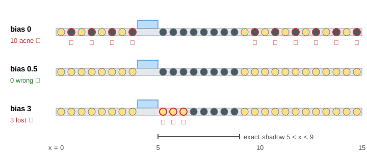
Too much bias goes wrong the other way. Next to the wall's foot the blocker and the floor are close in depth: point x = 5.25 has z = 8.2 and its texel stored the wall at 6.525, a gap of only 1.675. Bias 3 is bigger than that gap, so the point is lit. The first three shadow points (5.25, 5.75, 6.25) are lost and the shadow starts away from the wall, as if the wall floated. That is peter-panning, after the boy who lost his shadow. (Demo 6: bias 3, peter-panning)
| bias | points in shadow | wrong | looks like |
|---|---|---|---|
| 0 | 18 | 10 acne | stripes on the lit floor ✗ |
| 0.1 | 18 | 10 acne | still stripes: 0.1 < 0.2 ✗ |
| 0.5 | 8 | 0 | correct ✓ |
| 3 | 5 | 3 lost | gap at the wall's foot ✗ |
Real engines scale the bias with the slope of the surface to the light
(glPolygonOffset(factor, units) in OpenGL, the depth-bias and slope-scaled depth-bias
rasterizer settings in Direct3D), because a steeper surface has a bigger error per texel.
PCF: soft edges
A hard test gives each point 0 or 1, so the shadow edge is as blocky as the texels. Percentage-closer filtering (PCF) compares the point with several texels around its own and averages the yes/no answers. The page uses texels i − 1, i and i + 1, so a point gets 0, 1/3, 2/3 or 1 of the light. With bias 1.2, points 8.25 and 8.75 get 1/3 and points 9.25 and 9.75 get 2/3: the edge fades over two units of floor. (Demo 7: PCF 3 taps, soft edge)
PCF averages the results of the compares, not the depths. The average of 5.8 and 11.6 is a depth no surface has, and comparing with it would be just as hard-edged. The side taps also come from texels 0.8 nearer on the sloped floor, so PCF needs more bias: with bias 0.5 most of the lit floor gets only 2/3. Bias 1.2 is above 0.2 + 0.8 = 1.0 and still below the 1.225 gap at the wall's foot.
What the page leaves out
Spot lights use a perspective projection, and point lights a cube map of six shadow maps. Large outdoor
scenes use cascaded shadow maps (several maps for near and far). The page leaves out slope-scaled and
normal-offset bias, rendering back faces into the map to fight acne, hardware compare samplers
(sampler2DShadow, which also do a 2 × 2 PCF), depth stored as 0…1 with limited precision,
shadow-map resolution and aliasing, soft shadows that widen with distance (PCSS), and variance shadow maps.
How the lit points are coloured is on Phong Shading.