The idea: remember how much of the pattern you have seen
A sequence detector reads one bit per clock cycle and outputs 1 when the last bits are a given pattern, here 1011. It cannot store the whole stream. It only needs to know how much of 1011 the latest bits already match. That is its state:
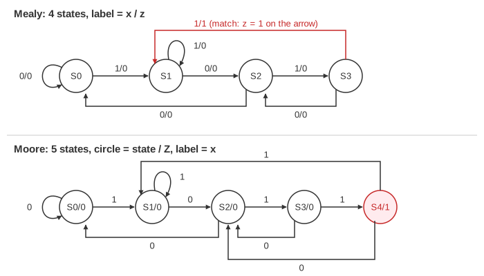
- S0: nothing useful seen yet;
- S1: the last bit was 1;
- S2: the last bits were 10;
- S3: the last bits were 101;
- and, in a Moore machine only, S4: the last bits were 1011, a match.
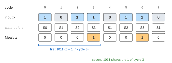
On the canvas, press Design Step six times to build the detector, then Clock Edge to feed the stream one bit per cycle. The general parts of a state machine (state register, next-state logic, output logic, encodings) are explained on Finite State Machines; this page is one complete worked design.
Stage 1: the forward path
Start in S0 and follow the pattern. Each correct bit moves one state forward: S0 –1→ S1 –0→ S2 –1→ S3 –1→ match. In a Mealy machine the last arrow carries the output, written x / z = 1/1. In a Moore machine the output belongs to a state, so the match needs a state of its own, S4, with Z = 1 inside it (Demo: build the Mealy 1011 detector, Demo: build the Moore 1011 detector).
Stage 2: where a wrong bit goes
Every state needs an arrow for both input values. A wrong bit does not always send the detector back to S0. Write down what was seen plus the new bit, and keep its longest end that is still a start of 1011:
| state | wrong bit | seen | longest end that starts 1011 | go to |
|---|---|---|---|---|
| S0 | 0 | 0 | none | S0 |
| S1 | 1 | 11 | 1 | S1 |
| S2 | 0 | 100 | none | S0 |
| S3 | 0 | 1010 | 10 | S2 |
The S3 row is the one people get wrong. After 101 a 0 gives 1010, and its end 10 is the start of a new 1011. Going back to S0 would miss the match in 1010110 (Demo: a wrong bit keeps 10: z = 1 in cycle 5). The S2 row really does start over: in 10010110 the 100 leaves nothing, and the match comes in cycle 6 (Demo: 100 starts over). This rule is the same failure function that the Knuth-Morris-Pratt string search builds.
Overlapping or not
After a match, the last 1 of 1011 could also be the first 1 of the next one. An overlapping detector counts it: Mealy S3 –1/1→ S1, and Moore S4 goes to S1 on 1 and to S2 on 0 (10110 ends with 10). A non-overlapping detector throws the match away and starts over: Mealy S3 –1/1→ S0, Moore S4 behaves like S0. On 10110110 the overlapping detector finds 2 matches, the non-overlapping one finds 1 (Demo: Mealy vs Moore on 10110110 and Demo: overlapping vs non-overlapping). Which one is right depends on the job: counting every occurrence, or finding separate packets.
Mealy or Moore
| Mealy | Moore | |
|---|---|---|
| output depends on | state and input x | state only |
| states for 1011 | 4 | 5 |
| D flip-flops | 2 | 3 |
| output equation | z = Q1·Q0·x | Z = Q2 |
| output is 1 | in the cycle of the last 1 | in the next cycle |
From diagram to circuit
- State table. One row per state, the next state (and Mealy output) for x = 0 and x = 1. It says exactly what the arrows say.
- State assignment. N states need ⌈log₂ N⌉ flip-flops: 4 states fit in 2 (S0..S3 = 00, 01, 10, 11), 5 need 3 (S0..S4 = 000 … 100). The Moore codes 101, 110 and 111 never occur, so they are don't cares.
- Equations. With D flip-flops, D is just the next value of its bit, so each D input is 1 in the table cells where that bit of the next state is 1. Group them on a Karnaugh map.
- Circuit. The equations become the next-state logic in front of the D inputs; the Q outputs feed back; one clock loads all flip-flops at once.
| machine | D inputs | output |
|---|---|---|
| Mealy, overlapping | D1 = Q0·x' + Q1·Q0'·x, D0 = x | z = Q1·Q0·x |
| Mealy, non-overlapping | D1 = Q0·x' + Q1·Q0'·x, D0 = Q1'·x + Q0'·x | z = Q1·Q0·x |
| Moore, overlapping | D2 = Q1·Q0·x, D1 = Q0·x' + Q2·x' + Q1·Q0'·x, D0 = Q1'·x + Q0'·x | Z = Q2 |
| Moore, non-overlapping | D2 = Q1·Q0·x, D1 = Q0·x' + Q1·Q0'·x, D0 = Q1'·x + Q0'·x | Z = Q2 |
Take D0 of the overlapping Mealy detector. Every arrow on a 1 goes to S1 or S3, the odd codes, and every arrow on a 0 goes to S0 or S2. So the next Q0 is just x: D0 = x. For JK or T flip-flops you would go through excitation tables instead, as on Flip-Flop and Counter Design.
Output timing: the same stream into both
The timing diagram on the canvas feeds the same bits into a Mealy and a Moore detector. In each cycle the Mealy z is computed from the state and the bit that is arriving, so it goes to 1 in the cycle of the last 1 of 1011. The Moore Z is read from the flip-flops, so it goes to 1 only after the clock edge has loaded S4, one cycle later, and then stays 1 for that whole cycle.
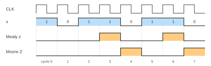
On 10110110 the overlapping detectors give Mealy z = 1 in cycles 3 and 6 and Moore Z = 1 in cycles 4 and 7. The Mealy answer is earlier, but it is a combinational path from the input to the output: a glitch on x is a glitch on z. The Moore answer is clean for a whole cycle. In the Demo: Moore circuit on 110110, Q2 Q1 Q0 = 100 during cycle 5, so Z = Q2 = 1. Building the flip-flops themselves from gates is on Sequential Logic.
What the page leaves out
- Other patterns and lengths. The method is the same for any pattern: one state per prefix, the longest-end rule for wrong bits.
- Unused Moore codes. The page never enters 101, 110 or 111. A real design checks where the equations send them after power-up, or uses a reset.
- Gate drawings and minimisation. The logic is drawn as two boxes with the equations; the K-map grouping is on its own page.
- Other encodings such as one-hot or Gray, and other flip-flop types.
- Delays. No gate or clock-to-Q delay, so no glitches appear and the input is one clean bit per cycle; a real asynchronous input needs a synchronizer.
On the mind map
References
Mano and Ciletti, Digital Design, chapter 5: analysis and design of clocked sequential circuits (state diagrams, state tables, state assignment, design with D flip-flops)
Harris and Harris, Digital Design and Computer Architecture, section 3.4: finite state machines, Moore and Mealy machines