The idea: one output from a few inputs, described three ways
A logic gate is a small circuit that takes one or more binary inputs (each 0 or 1) and produces one binary output, called Y here. Every gate can be described in three equivalent ways: by its symbol (the picture used in schematics), by its Boolean equation (Y = AB for AND), and by its truth table, which lists the output for every combination of inputs. A gate with N inputs has 2N combinations, so its truth table has 2N rows.
On the canvas one gate is drawn big. Click an input box (or press Next Row) to change the inputs. The wire of an input at 1 turns blue, then the gate answers: the output Y changes and the matching row of the truth table lights up. Walk Table goes through every row from 00…0 to 11…1, counting up in binary with A as the most significant bit. Pick a gate and the number of inputs in the two menus.
NOT and the buffer
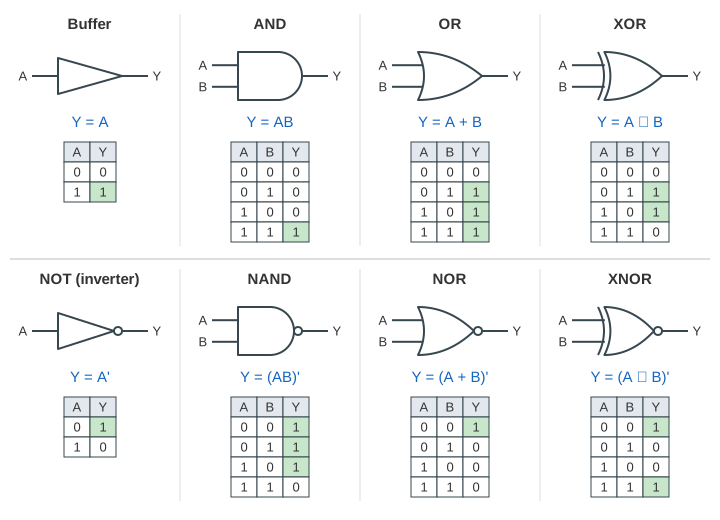
The NOT gate, or inverter, has one input A and outputs its opposite: Y = A', also written with a bar over the A and read "A bar" or "not A". Its symbol is a triangle with a small circle on the output. That circle, the bubble, means "invert here" wherever it appears. (Demo: NOT, both rows)
The buffer is the same triangle without the bubble: Y = A. Logically it does nothing. In real circuits it is used to drive a large load, such as many gates or a long wire, quickly: it delivers the same value with more current.
AND and OR
The AND gate outputs 1 only when all of its inputs are 1: Y = AB, also written A·B or A ∩ B. The OR gate outputs 1 when at least one input is 1: Y = A + B, also written A ∪ B. Here + means OR, not addition, and writing two variables next to each other means AND. (Demo: AND vs OR, all four rows)
| A | B | AND: Y = AB | OR: Y = A + B |
|---|---|---|---|
| 0 | 0 | 0 | 0 |
| 0 | 1 | 0 | 1 |
| 1 | 0 | 0 | 1 |
| 1 | 1 | 1 | 1 |
One way to remember them: a single 0 forces AND to 0, and a single 1 forces OR to 1.
NAND, NOR, XOR and XNOR
Put a bubble on the output of AND and you get NAND (NOT AND): Y = (AB)'. Its Y column is the AND column inverted, so it is 0 only when every input is 1. In the same way NOR = NOT OR: Y = (A + B)', which is 1 only when every input is 0. On the canvas these gates get an extra truth-table column with the value before the bubble, and a small "before bubble" tag above the symbol. (Demo: NAND = NOT(AND), the bubble)
The XOR (exclusive OR) gate outputs 1 when A or B is 1 but not both: Y = A ⊕ B. In other words, it is 1 when the inputs differ. Its symbol is the OR shape with a second curved line at the back. XNOR is XOR with a bubble, Y = (A ⊕ B)': it is 1 when the inputs are equal, so it works as a one-bit equality checker. (Demo: XOR vs XNOR)
| A | B | NAND | NOR | XOR | XNOR |
|---|---|---|---|---|---|
| 0 | 0 | 1 | 1 | 0 | 1 |
| 0 | 1 | 1 | 0 | 1 | 0 |
| 1 | 0 | 1 | 0 | 1 | 0 |
| 1 | 1 | 0 | 0 | 0 | 1 |
A two-input gate has 22 = 4 rows, and each row can be 0 or 1, so there are 24 = 16 different two-input functions. AND, OR, NAND, NOR, XOR and XNOR are the six that get their own symbols. NAND and NOR are special: each one alone is enough to build any other function.
Multiple-input gates and parity
AND, OR, NAND, NOR and XOR also come with 3, 4 or more inputs, drawn with more input lines on the same body. An N-input AND is 1 in exactly one row of its 2N rows, the one where every input is 1. An N-input OR is 0 in exactly one row, the one where every input is 0. A 3-input NOR, Y = (A + B + C)', is 1 only for 000. (Demo: 4-input AND and OR)
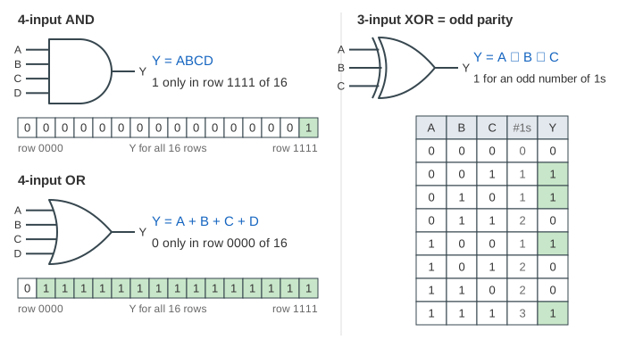
An N-input XOR is the parity function: Y = A ⊕ B ⊕ C is 1 when an odd number of the inputs are 1. That is why the canvas adds a "#1s" column for XOR gates. Parity is used to detect errors: a sender adds a parity bit so that every word has an even number of 1s, and the receiver XORs all the bits; a 1 means a bit flipped on the way. An N-input XNOR is 1 for an even number of 1s. (Demo: 3-input XOR = odd parity)
Gates as building blocks
Every digital circuit is built from these gates. A half adder is one XOR (the sum bit) and one AND (the carry); a multiplexer is a few ANDs feeding an OR.
See also Combinational Logic, where the same gates are wired into adders, a multiplexer, a decoder and an ALU and switch with real gate delays.
See also Karnaugh Maps, which turn any truth table into the smallest sum of AND terms.
See also Arithmetic Circuits, where XOR and AND gates become fast adders, comparators and a multiplier.
See also Number Bases: the rows of a truth table count up in binary, 00, 01, 10, 11.
What the page leaves out
The page treats gates as ideal: the output changes at once and every wire is exactly 0 or 1. Real gates are built from CMOS transistors, take time to switch (propagation delay) and treat a range of voltages as 0 or 1. It also leaves out tristate buffers (an output that can be switched off), bubble pushing with De Morgan's law, and building every circuit from NAND gates alone (NAND-NAND logic).
References
Harris and Harris, Digital Design and Computer Architecture, section 1.5 (Logic Gates): NOT, buffer, AND, OR, other two-input gates, multiple-input gates