The idea: what goes in must come out
Water hardly squeezes. So in a steady flow, every second the same volume of water must pass every cross-section of a pipe. That volume per second is the flow rate Q = A·v (area times speed). Where the pipe is narrow, the water must run faster:
This is the continuity equation. On the canvas the tracers keep a fixed spacing in the wide inlet and spread out in the throat: a quarter of the area means four times the speed, so each tracer covers four times the distance per step (Demo 1: continuity).
Bernoulli: P + ½ρv² + ρgz stays the same
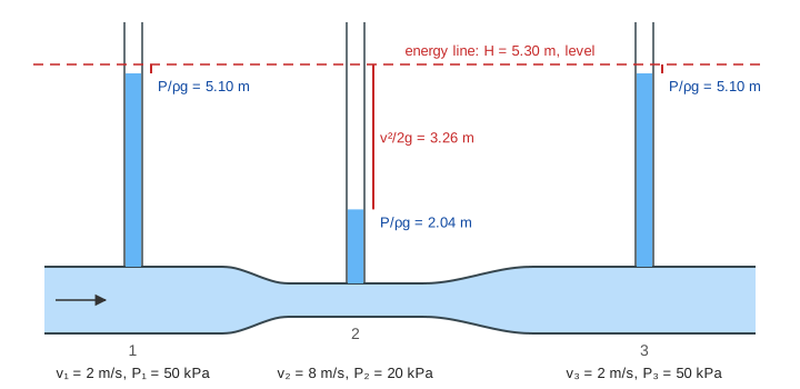
Follow one small parcel of water along a streamline. To speed up on its way into the throat, something must push it forward, and the only thing that can is the water behind it pushing harder than the water in front. So pressure falls where speed rises. Count the work done by pressure and gravity against the gain in kinetic energy and you get Bernoulli's equation:
It holds for a steady flow of a fluid that doesn't squeeze and has no friction. Each term is an energy per cubic metre: pressure energy, kinetic energy ½ρv², and height energy ρgz. Divide by ρg and each one becomes a height (a head):
| Term | As a head | On the canvas |
|---|---|---|
| pressure P | P/ρg | how high water rises in an open column |
| kinetic ½ρv² | v²/2g | the red gap from a column top up to the energy line |
| height ρgz | z | how high the pipe itself is above the datum |
| sum | H | the dashed energy line, level along the whole pipe |
With the page's numbers: P₁ = 50 kPa and v₁ = 2 m/s, a throat of A₁/4 runs at 8 m/s, so P₂ = 50 − ½·1000·(8² − 2²)/1000 = 50 − 30 = 20 kPa. The sum is 52 kPa at all three points. With no throat (Demo 2) all three columns stand level.
The Venturi meter
Turn it around: read the two columns and you know the flow. The difference Δh gives ΔP = ρgΔh. Put v₂ = v₁·A₁/A₂ into P₁ − P₂ = ½ρ(v₂² − v₁²) and solve:
A ½ throat at 3 m/s (Demo 3) gives Δh = 1.38 m, ΔP = 13.5 kPa, v₁ = √(2·13500 / (1000·3)) = 3 m/s and Q = 23.6 L/s. No moving parts, just two pressure taps: Venturi meters measure water, fuel and gas flows, and the carburettor and the aspirator use the same low pressure in a throat.
Uphill and suction
When the pipe climbs, ρgz grows, so pressure must give it up: 2 m of climb costs ρg·2 = 19.6 kPa and P₃ = 30.4 kPa (Demo 4). The column over the high pipe starts higher and still tops out at the same level. Speed up the water too much and the throat pressure drops below the air's: at 3 m/s into a ¼ throat, P₂ = 50 − 67.5 = −17.5 kPa gauge (Demo 5). An open tap there sucks air in. Push even further and the pressure reaches the water's vapour pressure: the water boils into bubbles that collapse hard further on (cavitation), which eats pump impellers and ship propellers.
How a wing lifts
A wing is curved and meets the air at a small angle of attack α. It turns the passing air downward (downwash), and even pulls the air ahead of it upward (upwash). Turning a flow takes a force: the wing pushes air down, so the air pushes the wing up. The same thing seen as pressure: the air going over the curved top speeds up and its pressure drops (the blue arrows on the canvas), the air underneath is slower and its pressure is higher (orange). The pressure difference over the wing's area is the lift. Both descriptions are true at once; they are the same force counted two ways.
The lift is written L′ = ½ρV²·c·C_L per metre of span, with chord c and a lift coefficient C_L that grows with α (about 0.1 per degree for a thin wing) until the flow separates and the wing stalls. On the canvas, a 1.5 m chord at 50 m/s and 4° gives C_L ≈ 1.03, about 2.4 kN per metre of span (Demo 6); at 8° the turning and the lift grow (Demo 7).
The equal-transit-time myth
A popular explanation says the air over the longer top surface must "catch up" with its partner from underneath at the trailing edge, so it goes faster. Nothing makes that happen, and it doesn't. Release a line of smoke and the air over the top arrives at the trailing edge well before the air underneath, and the two never meet again.
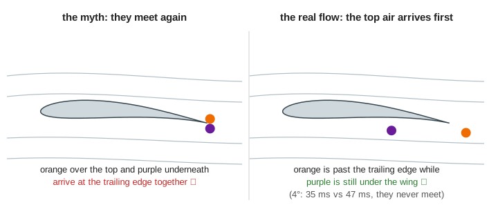
The myth also gets the size wrong. The top of a typical wing is only a few percent longer than the bottom, so "equal transit" would make the top air only a few percent faster, and the lift tiny: the canvas works it out as C_L ≈ 0.03 instead of 1.03. The real top-side speed comes from the wing turning the flow, not from the path length. It also could not explain a flat sail, a paper plane, or a plane flying upside down.
What the page leaves out
Real pipes have friction, so the energy line slopes down along the pipe (head loss, Darcy–Weisbach) and a Venturi meter needs a discharge coefficient of about 0.98. Fast flows are turbulent, and gases squeeze (compressible flow above about Mach 0.3). The wing is a 2-D potential flow round a Joukowski airfoil: the Kutta condition stands in for viscosity, which is what really sets the circulation; there is no boundary layer, no stall, no drag, and no wingtips (a real 3-D wing sheds tip vortices and keeps its downwash far behind it). The pipe is drawn not to scale.
See also projectile motion for energy and gravity without a fluid, and a block on a ramp for forces on a slope.